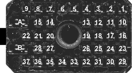
Cable's J1 connector front view pin out (cable on left side).
| System 90*s 32/16/8 Mode + Scan Head Cable Pinout Example |
|||
| - Description | |||
| - J1 Connector | |||
| - Black 22 Pin Connector | |||
| - #1 Gray 22 Pin Connector | |||
| - #2 Gray 22 Pin Connector | |||
| - #1 Light Purple 22 Pin Connector | |||
| - #2 Light Purple 22 Pin Connector | |||
| - Blue 6 Pin Connector | |||
| - Back to Cables | |||
| - Syntor X Home | |||
| - HOME | |||
Here is a typical negative ground pinout for a System 90*s TRN4344A (8 mode select), HLN4298A (4 bank select, volume, squelch and power) and a HLN4290A (8 mode operator select non-priority scan) control head . This is a 32 mode control head and an 8 mode System 90*s operator select non-priority scan select with display. The pinout is for the radio connector J1, control head conectors 22 pin black, 22 pin gray #1, 22 pin gray #2, 22 pin light purple #1, 22 pin light purple #2 and 6 pin blue. There are also wires that just connect from one control head connector to another control head connector.
The 16 mode version of this control head using the HLN4296A or TRN4340A (2 bank select, volume, squelch and power) board instead of the HLN4298A (above), has the same wiring except Mode 5 on pin 3 of the 6 pin blue connector and its wire is not used. The jumper selections on the TRN4344A will also be different.
The 8 mode version of this control head using the TRN4395A (volume, squelch and power) board instead of the HLN4298A (above) has the same wiring except the 6 pin blue connector and its 3 wires are not used at all. The jumper selections on the TRN4344A will also be different.
Cable's J1 connector front view pin out (cable on left side).
|
|
||||||
| J1 | 22 pin BLACK | 22 pin GRAY #1 | 22 pin GRAY #2 | 22 pin Lt. PURPLE #1 |
22 pin Lt. PURPLE #2 |
J1 DESCRIPTION |
| A | A+ (Red Wire) | |||||
| B | A- (jumpered to J1 pins 8 and 10) | |||||
|
|
11 | Control Head Strobe | ||||
|
|
16 | Detected Audio | ||||
|
|
20 | Volume - Receiver Audio | ||||
|
|
22 | PTT | ||||
|
|
14 | PTT Reference | ||||
|
|
Squelch Tail | |||||
|
|
Securenet Modulation | |||||
|
|
2 | Switched B- (jumpered to J1 pins 10 and B) | ||||
|
|
Switched B+ to Accessories | |||||
|
|
2 | Chassis (jumpered to J1 pins 8 & B) | ||||
|
|
10 | Mode 12 | ||||
|
|
3 | Mode 5 | ||||
|
|
8 | Mode 1 | ||||
|
|
21 | Shield | ||||
|
|
1 | Switched B+ | ||||
|
|
11 | Mode 6 | ||||
|
|
7 | Mode 2 | ||||
|
|
||||||
|
|
9 | Mode 10 | ||||
|
|
Transmit Indicator | |||||
|
|
Transmit Mode | |||||
|
|
6 | Speaker Audio Low | ||||
|
|
10 | Mode 7 | ||||
|
|
6 | Mode 3 | ||||
|
|
2 | Mode 4 | ||||
|
|
8 | Mode 9 | ||||
|
|
11 | Mic. High | ||||
|
|
17 | Squelch | ||||
|
|
5 | Mode 8 | ||||
|
|
7 | Mode 11 | ||||
|
|
1 | Channel Scan Enable {JU1 removed} | ||||
|
|
4 | PL/DPL Disable | ||||
|
|
3 | Display Enable {JU14 removed} | ||||
|
|
Sidetone In | |||||
|
|
EMS Mute | |||||
|
|
Transmit DVP | |||||
|
|
3 | Speaker Audio High | ||||
22 pin System 90*s connector rear view pin out.
|
|
|||||||
| PIN # | 22 pin GRAY #1 | 22 pin GRAY #2 | 22 pin Lt. PURPLE #1 |
22 pin Lt. PURPLE #2 |
6 pin BLUE | J1 | DESCRIPTION |
| 1 | 12 | Switched B+ | |||||
| 2 | Hang Up Box Gnd. | ||||||
| 3 | 37 | Speaker Audio | |||||
| 4-15 | 32 | PL/DPL Disable | |||||
| 5 | N.C. | ||||||
| 6-9 | 22 | Speaker Audio Low | |||||
| 7 | (Display Enable) {moved} | ||||||
| key | |||||||
| 9-6 | 13 | (Chassis) | |||||
| 10 | (Shield) | ||||||
| 11 | 27 | Mic. High | |||||
| 12 | A+ Unswitched (Green Wire) |
||||||
| 13 | A+ Ignition Switch (Orange Wire) |
||||||
| 14 | 5 | PTT Reference | |||||
| 15-4 | Hang Up Box Switched | ||||||
| 16 | 2 | Detected Audio | |||||
| 17 | 28 | Squelch | |||||
| key | |||||||
| 19-21 | (Shield) | ||||||
| 20 | 3 | Volume - Receiver Audio | |||||
| 21-19 | 14 | Shield | |||||
| 22 | 4 | PTT | |||||
|
|
|||||||
| PIN # | 22 pin BLACK | 22 pin GRAY #2 | 22 pin Lt. PURPLE #1 |
22 pin Lt. PURPLE #2 |
6 pin BLUE | J1 | DESCRIPTION |
| 1-12 | 12 | Switched B+ | |||||
| 2-3-13 | 13 | Switched B-, J1-10 Chassis | |||||
| 3-2-13 | 33 | (Switched B-) | |||||
| key | |||||||
| 5 | |||||||
| 6 | |||||||
| 7-17 | 30 | Mode 11 | |||||
| 8-18 | 26 | Mode 9 | |||||
| 9-19 | 19 | Mode 10 | |||||
| 10-20 | 11 | Mode 12 | |||||
| 11-22 | 1 | Control Head Strobe | |||||
| 12-1 | 1 | (Switched B+) | |||||
| 13-2-3 | 9 | (Switched B-) | |||||
| key | |||||||
| 15 | |||||||
| 16 | |||||||
| 17-7 | 7 | (Mode 11) | |||||
| 18-8 | 8 | (Mode 9) | |||||
| 19-9 | 9 | (Mode 10) | |||||
| 20-10 | 10 | (Mode 12) | |||||
| 21 | 4 | Mode Strobe | |||||
| 22-11 | 11 | (Control Head Strobe) | |||||
|
|
|||||||
| PIN # | 22 pin BLACK | 22 pin GRAY #1 | 22 pin Lt. PURPLE #1 |
22 pin Lt. PURPLE #2 |
6 pin BLUE | J1 | DESCRIPTION |
| 1-12 | 15 | Switched B+ | |||||
| 2-3-13 | 8 | Switched B-, J1-10 Chassis | |||||
| 3-2-13 | (Switched B-) | ||||||
| key | |||||||
| 5 | |||||||
| 6-16 | |||||||
| 7-17 | 17 | Mode 11 | |||||
| 8-18 | 18 | Mode 9 | |||||
| 9-19 | 19 | Mode 10 | |||||
| 10-20 | 20 | Mode 12 | |||||
| 11-22 | 22 | Control Head Strobe | |||||
| 12-1 | 1 | (Switched B+) | |||||
| 13-2-3 | 2 | (Switched B-) | |||||
| key | |||||||
| 15 | |||||||
| 16-6 | |||||||
| 17-7 | (Mode 11) | ||||||
| 18-8 | (Mode 9) | ||||||
| 19-9 | (Mode 10) | ||||||
| 20-10 | (Mode 12) | ||||||
| 21 | Mode Strobe | ||||||
| 22-11 | (Control Head Strobe) | ||||||
|
|
|||||||
| PIN # | 22 pin BLACK | 22 pin GRAY # 1 | 22 pin GRAY # 2 | 22 pin Lt. PURPLE #2 |
6 pin BLUE | J1 | DESCRIPTION |
| 1 | |||||||
| 2-12 | 25 | Mode 4 | |||||
| 3-14 | 12 | Mode 5 | |||||
| key | |||||||
| 5-16 | 29 | Mode 8 | |||||
| 6-17 | 24 | Mode 3 | |||||
| 7-18 | 17 | Mode 2 | |||||
| 8-19 | 13 | Mode 1 | |||||
| 9 | |||||||
| 10-21 | 23 | Mode 7 | |||||
| 11-22 | 16 | Mode 6 | |||||
| 12-2 | 2 | (Mode 4) | |||||
| key | |||||||
| 14-3 | 3 | (Mode 5) | |||||
| 15 | |||||||
| 16-5 | 5 | (Mode 8) | |||||
| 17-6 | 6 | (Mode 3) | |||||
| 18-7 | 7 | (Mode 2) | |||||
| 19-8 | 8 | (Mode 1) | |||||
| 20 | |||||||
| 21-10 | 10 | (Mode 7) | |||||
| 22-11 | 11 | (Mode 6) | |||||
|
|
|||||||
| PIN # | 22 pin BLACK | 22 pin GRAY # 1 | 22 pin GRAY # 2 | 22 pin Lt. PURPLE #1 |
6 pin BLUE | J1 | DESCRIPTION |
| 1 | 31 | Channel Scan Enable | |||||
| 2-12 | 12 | Mode 4 | |||||
| 3-14 | 14 | Mode 5 | |||||
| key | |||||||
| 5-16 | 16 | Mode 8 | |||||
| 6-17 | 17 | Mode 3 | |||||
| 7-18 | 18 | Mode 2 | |||||
| 8-19 | 19 | Mode 1 | |||||
| 9 | |||||||
| 10-21 | 21 | Mode 7 | |||||
| 11-22 | 22 | Mode 6 | |||||
| 12-2 | 1 | (Mode 4) | |||||
| key | |||||||
| 14-3 | 3 | (Mode 5) | |||||
| 15 | |||||||
| 16-5 | (Mode 8) | ||||||
| 17-6 | (Mode 3) | ||||||
| 18-7 | (Mode 2) | ||||||
| 19-8 | (Mode 1) | ||||||
| 20 | |||||||
| 21-10 | (Mode 7) | ||||||
| 22-11 | (Mode 6) | ||||||
6 pin System 90*s connector rear view pin out.
|
|
|||||||
| PIN # | 22 pin BLACK | 22 pin GRAY #1 | 22 pin GRAY #2 | 22 pin Lt. PURPLE #1 |
22 pin Lt. PURPLE #2 |
J1 | DESCRIPTION |
| 1 | 12 | Mode 4 {16* & 32 mode control heads} | |||||
| key | |||||||
| 3 | 14 | Mode 5 {32* mode control heads} | |||||
| 4 | 21 | Mode Strobe | |||||
| 5 | DVP Audio In | ||||||
| 6 | |||||||
--
PL, Private Line, DPL, Digital Private Line, MPL, Talkaround, MDC-600, MDC-1200, MVS-20, Securenet, Smartnet, Privacy Plus, Trunked X2, Trunked X3, Touch Code, Quick Call II, Channel Scan, Talkback Scan, System 90, System 90*s, Systems 9000, Mitrek, Micor, Spectra, MataTrac, Syntor, Syntor X, Syntor X 9000 and Syntor X 9000E are trademarks of Motorola Inc.